Here is the 13 x 10 CNC Kit - it works! Let's add Limit Switches.

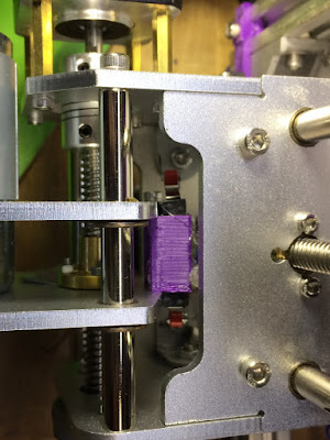
So I wanted to design a holder that didn't need screws to secure the switch. The design uses a post and a pin to hold the switch in the holder. Here you can see the switch with a proud pin.

Pin was been inserted.

X axis switch.

Y axis switch.

Z axis switch - taping holder - will replace existing hex standoff.

The rear hex standoff - not sure if I can get it installed without taking it completely apart.

Had to take the top screws out.

Install and solder to two switches.

Back together - hot mess of glue to hold the wires in place

Using the grbl guide for optocouplers found here: https://github.com/gnea/grbl/wiki/Wiring-Limit-Switches
Testing the limit switch control board - using long wires didn't work once the spindle fires up it trips. I tried using an older board that was laying around from another project that had these optocouplers on them - want a waste of time two are bad so I just ganged new ones on top of the non-working ones.

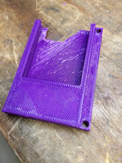
First bracket - needed to cut the back for the wire clearance. I designed it to replace the existing 4mm spacers behind the main control board - got the hole positions and distances right on the first go.


My input wires are too short - so I jumper them. I thought for sure I would continue to get spurious but it worked! So it's only the negative wire that needs to be short.

Second print - make it thicker and moved the slots that hold the board for more back clearance for the wire. Once I figured out that only the negative wire was receiving interference I moved the input wires back to the front.

10T85 Switch: https://smile.amazon.com/gp/product/B00MFRMFS6
Thingiverse Files: https://www.thingiverse.com/thing:2775407
No comments:
Post a Comment